Electrolumination
This page documents my effort with with electrolumination for the Angstloch project. There's information to be found elsewhere on the Internet about using EL for various purposes. On this page I will describe how I apply EL paint directly to a circuit board such that the embedded copper traces or pours provide the backplane. I build driver circuitry into the same PCB to produce a standalone EL product. With careful design and layout, this process produces very cool results.
Warnings
Working with eletrolumination is expensive. As a ballpark estimate, the paint alone can cost as much as $400 per square foot of coverage. It requires the right equipment, a great deal of care, tedious attention to detail, and dealing with potentially dangerous high voltage. That aside, it's really really cool.
EL Material Suppliers
These are the suppliers from which I've obtained EL materials.
- Lumilor (via online resellers)
- PEDOT Inks, aka glowbug20
Design Process
TODO
Application Process
Lumilor
Begin by watching Lumilor's training series for applicators. I recommend watching all of the videos and reading all of the information you can find.
Preparation
I use the following equipment for applying Lumilor:
- 2x Paasche HG-08 HVLP spray guns
- A Master Airbrush G22 airbrush (w/ 0.5mm needle)
- A Master Airbrush S622 Hi-Glow airbrush (w/ 0.8mm needle)
- A 2 gallon air compressor with water trap, pressure gauge, high quality air-lines, and quick disconnects
- A spray booth with exhaust fan
- A respirator
- Latex free vinyl gloves
- 3M 06404 Vinyl Tape Scotch (3mm)
- 3M 08987 Performance Masking Tape (3mm and 6mm)
- Kimberly-Clark lint free shop towels
- Acetone
You can get by with a lot less than this, but I recommend that anyone looking to apply this stuff not skimp on their respirator, exhaust setup, or gloves. Good quality safety equipment will help keep you safe.
I also recommend purchasing quality masking tape designed for automotive pin striping. It's very expensive, but it performs very well.
Process
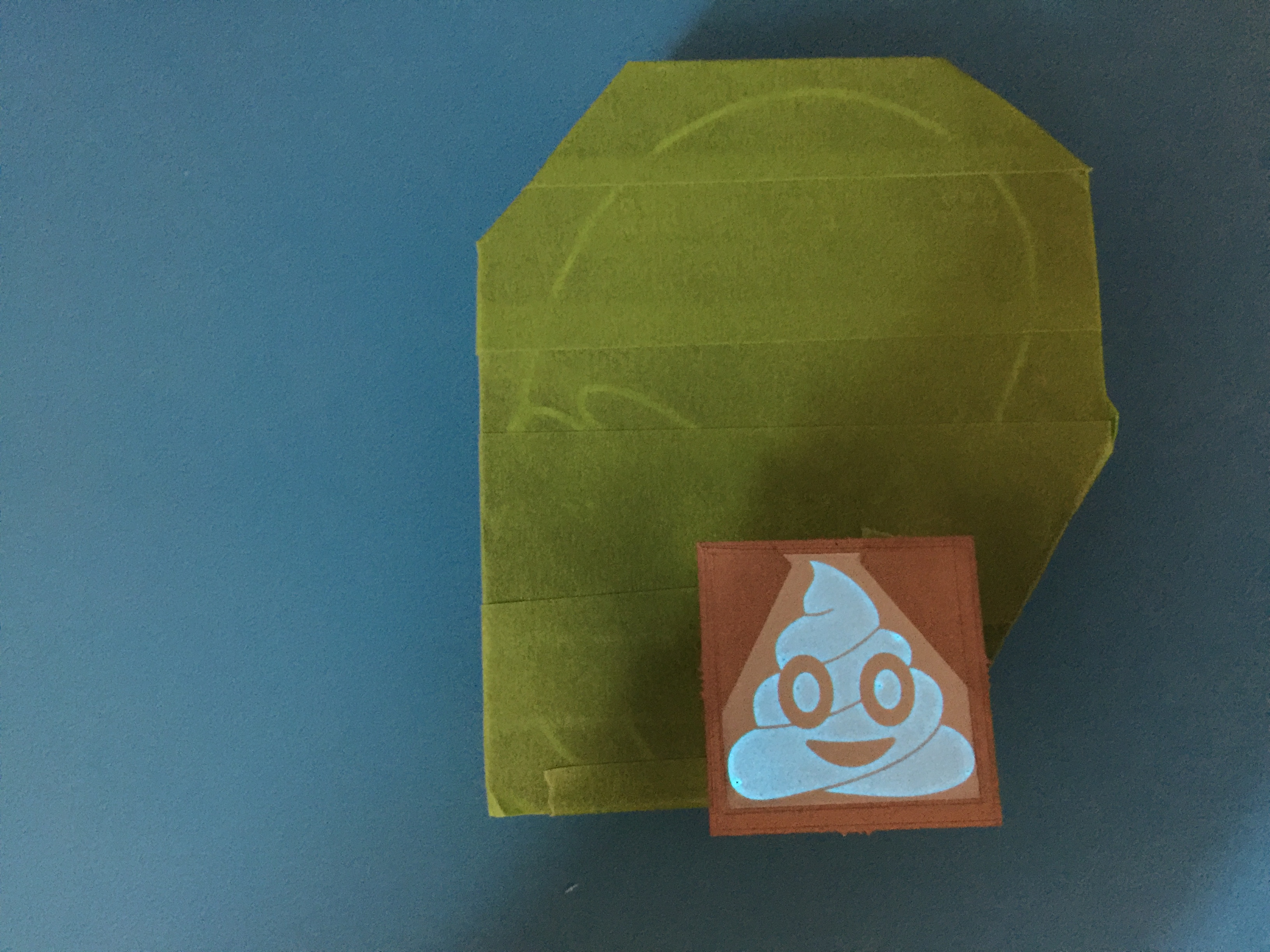
Lumilor is applied in four layers. It would be five, except that we don't apply a backplane layer. We'll put the first layer of dielectric material directly on the exposed conductive surface of our PCB. My PCBs are designed with a "bus bar" built in, in the form of a boarder around the true "backplane." I begin by masking the bus bar off with vinyl tape and spraying a layer of dielectric. The dielectric goes on more-or-less in accordance with the standard Lumilor instructions. I do two passes with a 0.8mm HVLP spray gun at about 30 PSI, flash for 15 minutes, and then another two passes. The dielectric is then left to dry for 1-2 hours.
The second step is something I've experimented with. After 1-2 hours, I remove the masking:

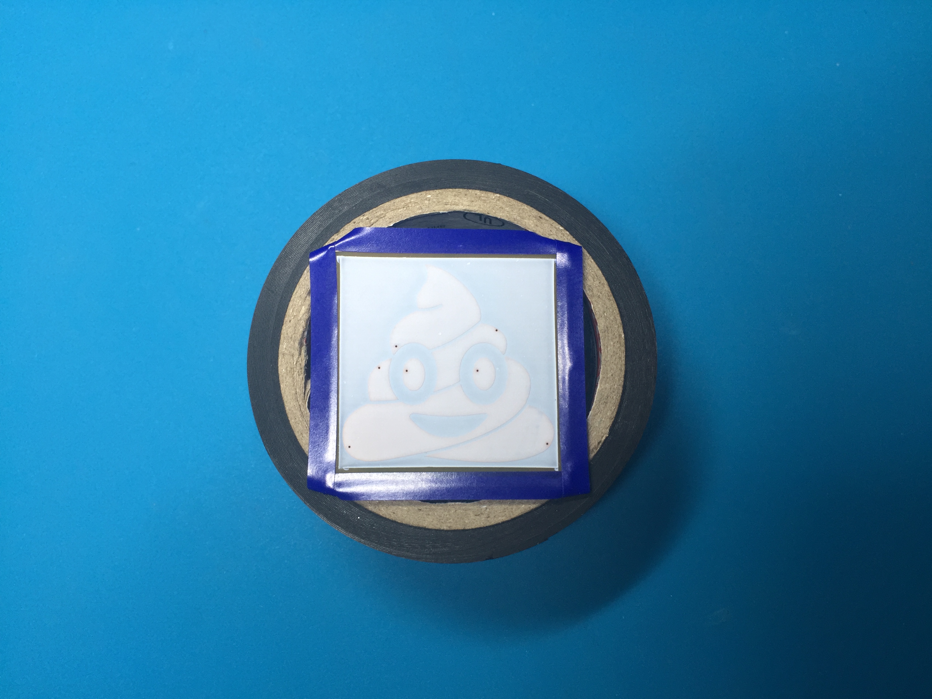
I next re-mask the board leaving a small gap between the edge of the first layer and the new tape lines. This allows the second material application (the EL paint itself) to completely cover the first layer. This step is optional and not strictly necessary, but I've found it produces a more evenly lit final product in my designs. I suspect that much wider margins between the backplane and bus bar would help as well, but my early designs have all been fairly tight.
The second layer of material is applied the same as the first; two passes with a 0.8mm HVLP spray gun at 30 PSI, 15m flash, and then two more passes before a 1-2 hour cure period. Lumilor recommends doing this under black light. I don't, but I do check each layer under a black light after applying it.
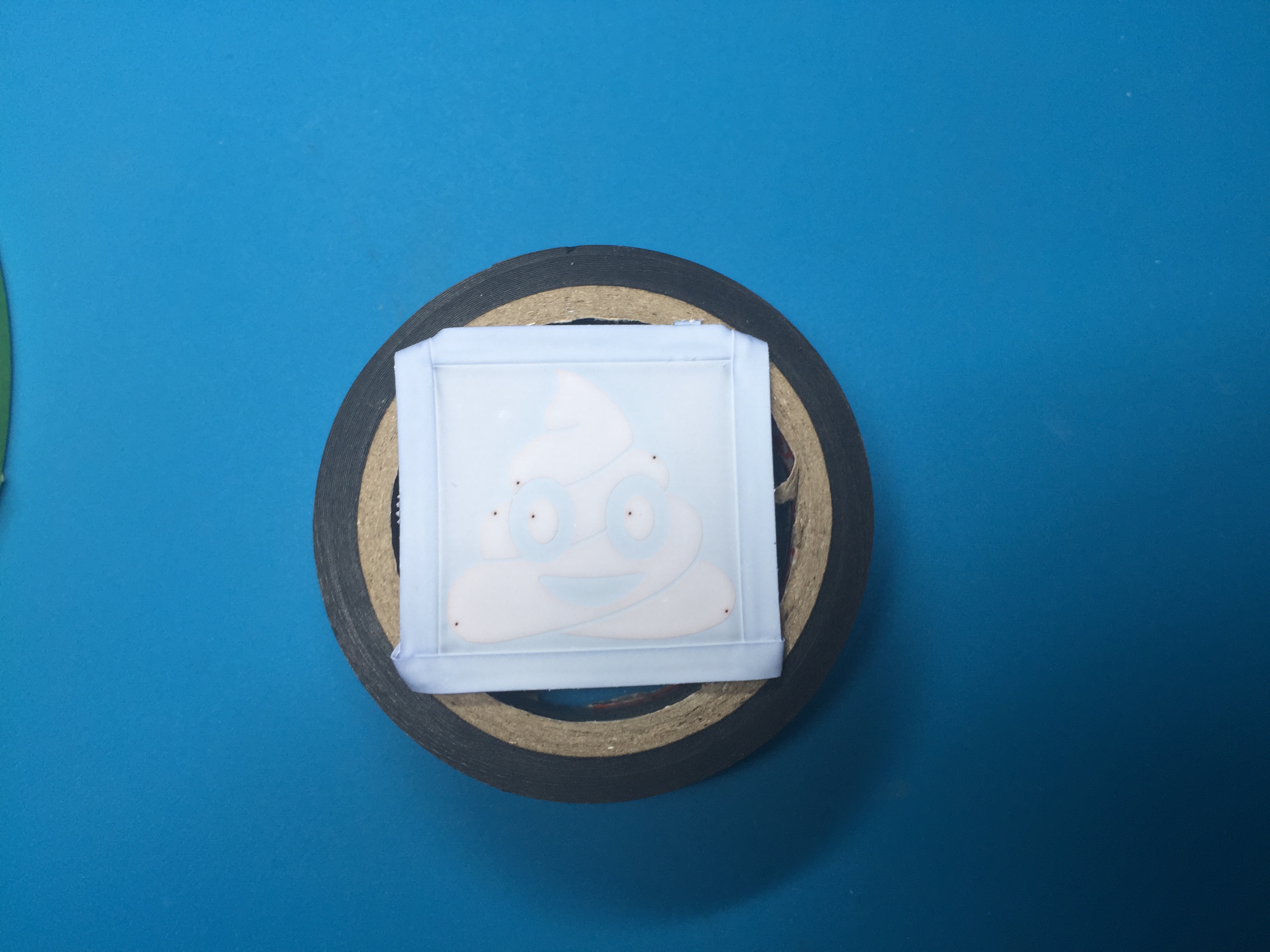
After the EL layer cures, I will remove the masking material and apply a third layer of masking. This next sequence is also optional and I've yet to determine exactly how useful it is. What I do here is to apply, using the Lumilor backplane material, a bus bar according to the manufacturer's guidelines. Lumilor prescribes a bus bar with 1/3 the total surface area of the backplane. I'm not sure of all the factors that play into why this recommendation is what it is. I believe a major factor is the resistance of the backplane material itself, which is non-zero. As my designs have a bus bar etched into the PCB itself (which is a copper trace with an ENIG surface finish), I'm not worried about the overall resistance of the bus bar. Still, what I do here is to re-mask such that a thin strip of the EL layer will be coated by the bus bar material. I also ensure that bus bar material I will be laying down comes into direct contact with the etched bus bar.
In my first attempts, I ignored this step entirely and simply applied the conductive topcoat directly over the EL and the etched bus bar. I did experience a few board samples that had shorts, which was likely due to a poor job of masking or using the wrong masking material (paper tape instead of vinyl) rather than the process. Those early boards lit decently well, but I believe I'm producing slightly better illumination by adding an extended bus bar as described here.

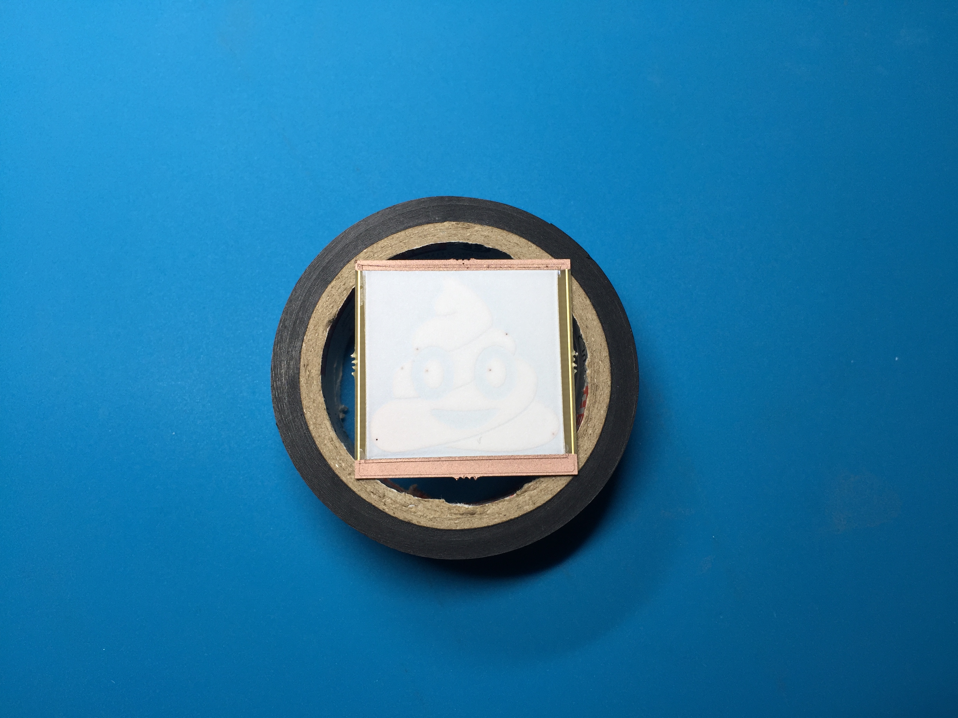
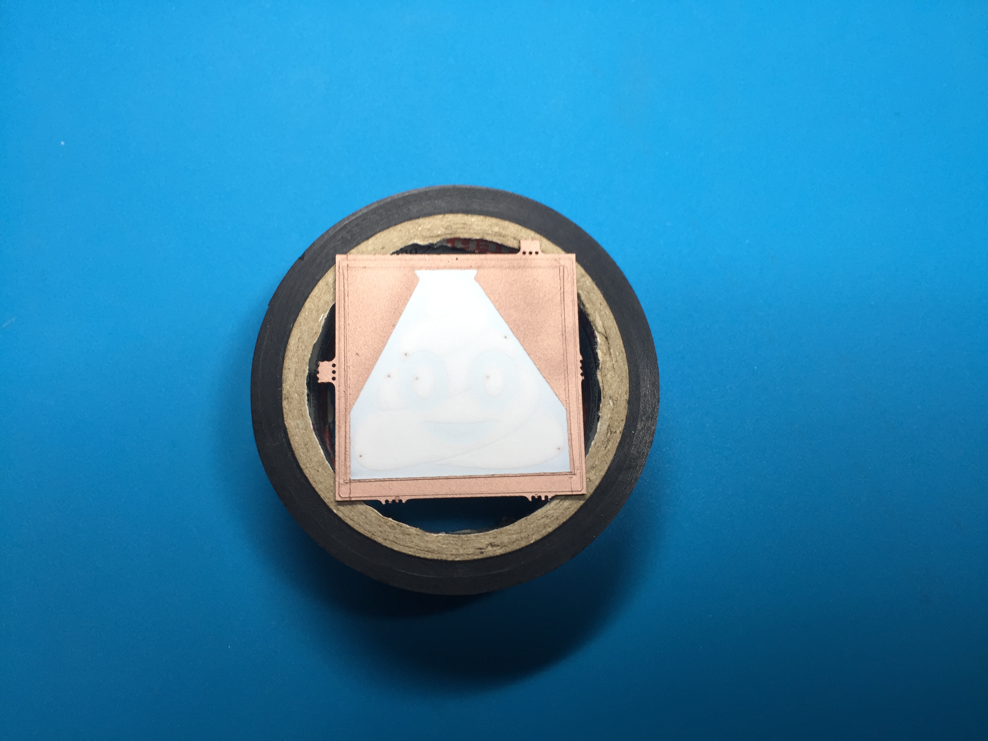
The bus bar goes down in multiple steps to masking easier. For some designs I even fill "empty" corners or spaces with more EL material, although in very small sizes (the illustrated board is only, in total, just over 1sq inch in size), I don't believe this make any difference at all in the final product.
The bus bar is applied with a smaller hand-held airbrush (a gravity fed model with a 0.5mm needle at about 25 PSI). I spray 5-10 layers of material in even passes, flash for 15m, and then apply another 5-10 layers. This is because the smaller airbrush sprays much less material than the larger HVLP guns, even at the same pressure. When sprayed thusly, the backplane material dries almost instantly.
After 1-2 hours of cure time, I will remove the masking tape.

After the final masking layer is removed, I apply a thin coating of the Lumilor clear topcoat with a siphon fed hi-flow airbrush (0.8mm needle at about 25 PSI). The topcoat material is water based and very thin, so it applies much like a traditional airbrush paint does. I speed dry this coating with a heat gun (I actually use my hot air rework station with the heat turned as low as it will go), under power.